Universal Heavy Duty Rife Ram Pump 10HDU
$2,225.00
Out of stock
Description
What is a Ram?
The Universal Heavy Duty Rife Ram Pump RIFE 10HDU are devices for pumping water solely by means of water-power. The flow and fall of the water powers the Rife Ram, driving a portion of this water uphill. This provides a continuous supply of water day after day, year after year, without interruption in service.
Given a steady supply of water, a Ram is the closest thing to a perpetual motion machine.
Since the device does not require electricity, there are no operating costs, making the Rife Ram system a highly cost efficient one. In addition, Rife Rams are self-starting and require no lubrication or priming.
How it Works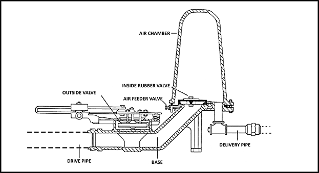
Briefly, here’s how a Rife Ram operates: Water flows down the Drive Pipe to the Ram, developing power in accordance to its weight and velocity. The water then flows through the Outside Valve until it reaches a certain velocity. The Valve then closes shut and water continues through the Inside Rubber Valve. When the water pressure in the Air Chamber equalizes and overcomes the driving force behind it, the water in the Drive Pipe rebounds, or backs up. When the rebound takes place a small amount of air is in sucked through the Air Feed Valve and lodged in the upper portion of the Base. It is then forced into the Air Chamber when the next blow takes place; this prevents the Air Chamber from filling up with water.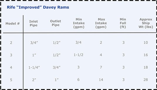
This operation is repeated from 25 to 100 times per minute working on a Hydraulic principle, building up pressure in the Air Chamber, which in turn forces water through the Delivery Pipe up to where it is desired.
What you will need to know…
Determining the Flow, Fall and Elevation
For each installation, the following information is necessary: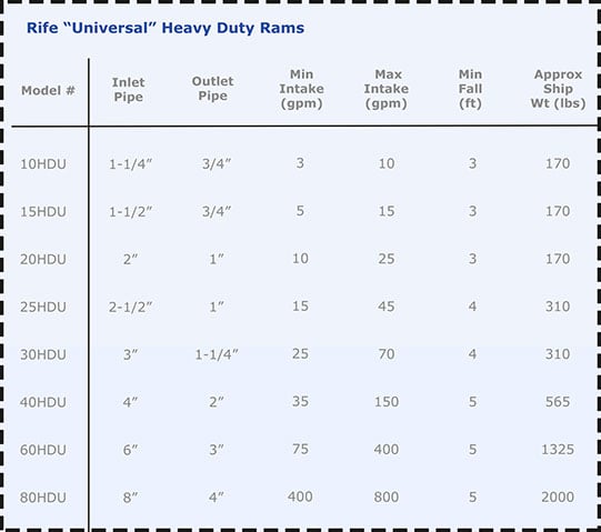
- The Flow of water at the source of Supply (in gallons per minute).
- The vertical Fall (in feet) from the source of Supply to the planned location of the Ram.
- The vertical Elevation above the Ram to which the water is to be pumped.
- The distance between the point of Supply and the Ram location, as well the pipe line distance over which the water is to be delivered.
- The number of gallons required per day.
Flow of Supply Water Available In Gallons Per Minute
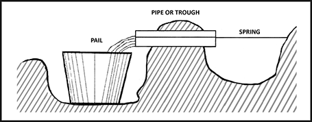
Time the Flow from the Supply in gallons per minute as accurately as possible. Do not guess this-be sure to measure it. If the supply is low, run the water into a bucket or tub of known capacity. This measurement should be taken during the driest season of the year. See Figure 3.
If the water flow is large and it is not practical to measure Flow with a bucket of tub, use a “Weir” (notch in a board).
Measure the width of the notch W and the height of the water in the notch H. The height should be measured on a level 2 feet Upstream from the notch as in Figure 4.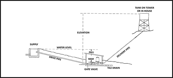
This table gives the number of cubic feet of water that will pass over a weir 1 inch wide and from 1/8 to 10 7/8 inches in depth. The figures in the first upright column represent whole inches and those in the top horizontal line represent fractional parts of an inch of depth over the weir. The figures in the second upright column indicate the number of cubic feet or water that will flow per minute over the weir for whole inches in depth, and in succeeding columns, whole inches and fractions under which they occur. Then the number of cubic feet thus found, multiplied the width of the weir in inches, will give the capacity of the stream.
Example: to find the required number of cubic feet of water that will flow over a weir 4-3/4 inches in depth and 30 inches in width, follow down the left hand column of figures in table to four, then across until directly under the .750 in the top line, to 4.14; this, multiplied by 30 (width of the notch in the weir) will give 124, the number of cubic feet of water that passes over the weir per minute. To reduce to gallons per minute, multiply by 7.5 to get 930 gallons per minute.
Determining The Vertical Fall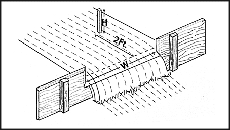
The difference in vertical elevation between the level of the water at the source and the planned location of the Ram is known as the Fall. This can be easily and quickly measured by using an ordinary carpenter’s level on a stick. Start at the planned location of the Ram and go upwards, as shown in the following illustration.
Bear in mind that, all other conditions being the same, the more Fall available, the more water the Ram will pump. For example, the Ram will pump twice as much water with a Fall of 8 feet as it would with a Fall of 4 feet. Therefore, it is advisable to take advantage of as much Fall as possible. In most cases, merely locating the Ram further downstream will provide more Fall.
Vertical Elevation
The vertical Elevation is the height to which the water will be pumped above the Ram location. It too can be easily determined by using an ordinary carpenter’s level on a stick as illustrated in Figure 5. Start measurements at the planned location of the Ram and work upward to the highest point at which water will be delivered.
Fig 5. A simple means of measuring fall.
Installation of Rams
Drive Pipe
The Drive Pipe should be metal, (usually galvanized steel), unless encased in concrete. In some cases people have successfully used well-anchored PVC plastic pipes. However, for trouble-free operation we recommend that the Drive Pipe be galvanized steel. It should be straight as possible without elbows, and normally the same pipe size as Intake end of the Ram. It should be watertight and rigidly anchored, with a Strainer at the source end to keep out refuse from the Ram. See Figure 6.
The Drive Pipe itself must be of the correct length. Use the following guidelines:
3-15 feet = 6 times length of Vertical Fall
16-25 feet = 4 times length of Vertical Fall
26-50 feet = 3 times length of Vertical Fall
Whenever distances exceed the lengths suggested above or when special conditions exist, please ask us for the correct length and diameter of Drive Pipe to assure maximum delivery.
Fig 6 Usual Drive Pipe arrangement when Supply is nearby. If supply is distant, call us for instructions.
Foundation and Ram Pit
A concrete slab or a large flat rock provides a good solid foundation on which to set the Ram. The best procedure is to put in a concrete slab as a foundation, slightly sloping towards the rear where the unused water will be carried away. After the Drive Pipe and Delivery Pipe are installed and the Ram is in operation, the Ram should be enclosed in a Concrete Pit. The Ram Pit should be large enough to give a clearance of 18 inches from the Ram on all sides in cases any bolts need to be replaced. The Pit should be high enough to prevent flood water from getting in. A sloping shed roof of boards provides good cover, yet, in colder climates it is better to cover the Pit with a concrete slab to prevent freezing. Use a manhole or a metal cistern for an opening to the Ram Pit.
Delivery Pipe
The correct size Delivery Pipe should match the dimension given for each particular size of Ram. Do not install a Delivery Pipe smaller than that is specified. By doing so you increase the amount of friction lost, consequently reducing the amount of water delivered. Avoid right-angled elbows wherever possible. This will minimize friction loss. Do not fill the ditch until the Ram is started and in operation. That way, leaks can be easily located and stopped before water covers the Delivery Pipe.
The installation of a Gate Valve in the Delivery Pipe at the Ram is a great convenience for cutting off water when it is necessary to adjust or too repair a Ram. The ditch for Delivery Pipe should be sufficiently below the frost line.
In case the Delivery Line goes over the top of a hill and down into a valley on its way from the Ram to the delivery point, a small Air Release Valve or Pet Cock should be installed in the Delivery Pipe at the highest point to release accumulations of air from time to time. Otherwise, accumulated air will restrict the free flow of the water.
The overflow pipe should also enter the bottom of the reservoir and terminate with a sleeve joint connection. Into this sleeve joint should be screwed a piece of pipe, the length of which determines the height of water in the reservoir. An emergency overflow should be provided at the top of the reservoir a few inches above the level of the regular overflow.
Drain Tile
The Ram Pit should be provided with a Drain Tile to carry off unused water. In many cases the total amount of fall can be increased by sinking the Ram Pit deep into the ground and carrying off the unused water though a long line of Drain Tiles of sufficient length to bring it out at water level downstream. In other cases, it is a choice between increasing the length of the Supply Pipe or running a line of Drain Tile. Usually, it is cheaper to use more tile and less pipe.
General Instructions For Installing Rife Rams
Rife Rams are easy to install when instructions are closely followed. There are many different ways Rams can be installed, depending mainly on the lay and character of the ground and other local conditions.
If your conditions are different from those described here or elsewhere in this Manual, please write to us giving full details of your conditions. We will advise you in writing on the proper method of installing the Ram.
Calculating Water Delivered
Once you know the Flow, Fall, Vertical Elevation, and distances to and from the Ram, you are ready to calculate the amount of water the Ram will deliver to you. Multiply the available Flow in gallons per minute (V) by the Vertical Fall in feet (F). Divide that by the vertical Elevation (E). Multiply the result by 0.6 (60%), the normal efficiency of a Rife Ram installation:
V x F/E x 0.6 = D
Download our Ram Situation Calculator to use this formula without the math!
>Ram Situation Calculator
This will give you the Delivery (D) in gallons per minute using all the available water supply. To obtain gallons per hour, multiply this amount by 60. For gallons per day, multiply by 1440.
NOTE: The amount of water used and pumped by RIFE Hydraulic Rams increases with increase in the Vertical Fall from the source of Supply to the Ram, and with increased lift of the Lever Rest during the stroke. This lift determines the opening of the Outside Valve and is adjustable. The range of intake capacity of each model and size of Rife Rams is listed in the Table entitled “Specifications of RIFE Rams” on the back cover of page.
Example
A Rife Ram, using a vertical Fall of 12 feet, pumping to an Elevation of 125 feet, will deliver 5.7% of the water used. For a Model 30BU Rife Ram, using 40 gallons per minute, this would be about 2.28 gallons per minute. One gallons per minute=60 gallons per hour, or 1440 gallons per day.
More water can be obtained by installing two or more rams in parallel. On irrigation, municipal water supplies and other large projects, a battery of two or more Rife Rams offers unlimited possibilities for an efficient and economical water system. It is often desirable to install two medium sized Rams to pump the same amount of water as one larger sized ram. With a battery installation, the number of Rams in operation can be governed by the amount of water required.
Drive Pipe
The Drive Pipe should be metal, (usually galvanized steel), unless encased in concrete. In some cases people have successfully used well-anchored PVC plastic pipes. However, for trouble-free operation we recommend that the Drive Pipe be galvanized steel. It should be straight as possible without elbows, and normally the same pipe size as Intake end of the Ram. It should be watertight and rigidly anchored, with a Strainer at the source end to keep out refuse from the Ram. See Figure 6.
The Drive Pipe itself must be of the correct length. Use the following guidelines:
3-15 feet = 6 times length of Vertical Fall
16-25 feet = 4 times length of Vertical Fall
26-50 feet = 3 times length of Vertical Fall
Whenever distances exceed the lengths suggested above or when special conditions exist, please ask us for the correct length and diameter of Drive Pipe to assure maximum delivery.
Foundation and Ram Pit
A concrete slab or a large flat rock provides a good solid foundation on which to set the Ram. The best procedure is to put in a concrete slab as a foundation, slightly sloping towards the rear where the unused water will be carried away. After the Drive Pipe and Delivery Pipe are installed and the Ram is in operation, the Ram should be enclosed in a Concrete Pit. The Ram Pit should be large enough to give a clearance of 18 inches from the Ram on all sides in cases any bolts need to be replaced. The Pit should be high enough to prevent flood water from getting in. A sloping shed roof of boards provides good cover, yet, in colder climates it is better to cover the Pit with a concrete slab to prevent freezing. Use a manhole or a metal cistern for an opening to the Ram Pit.
Delivery Pipe
The correct size Delivery Pipe should match the dimension given for each particular size of Ram. Do not install a Delivery Pipe smaller than that is specified. By doing so you increase the amount of friction lost, consequently reducing the amount of water delivered. Avoid right-angled elbows wherever possible. This will minimize friction loss. Do not fill the ditch until the Ram is started and in operation. That way, leaks can be easily located and stopped before water covers the Delivery Pipe.
The installation of a Gate Valve in the Delivery Pipe at the Ram is a great convenience for cutting off water when it is necessary to adjust or too repair a Ram. The ditch for Delivery Pipe should be sufficiently below the frost line.
In case the Delivery Line goes over the top of a hill and down into a valley on its way from the Ram to the delivery point, a small Air Release Valve or Pet Cock should be installed in the Delivery Pipe at the highest point to release accumulations of air from time to time. Otherwise, accumulated air will restrict the free flow of the water.
The overflow pipe should also enter the bottom of the reservoir and terminate with a sleeve joint connection. Into this sleeve joint should be screwed a piece of pipe, the length of which determines the height of water in the reservoir. An emergency overflow should be provided at the top of the reservoir a few inches above the level of the regular overflow.
Drain Tile
The Ram Pit should be provided with a Drain Tile to carry off unused water. In many cases the total amount of fall can be increased by sinking the Ram Pit deep into the ground and carrying off the unused water though a long line of Drain Tiles of sufficient length to bring it out at water level downstream. In other cases, it is a choice between increasing the length of the Supply Pipe or running a line of Drain Tile. Usually, it is cheaper to use more tile and less pipe.
General Instructions For Installing Rife Rams
Rife Rams are easy to install when instructions are closely followed. There are many different ways Rams can be installed, depending mainly on the lay and character of the ground and other local conditions.
If your conditions are different from those described here or elsewhere in this Manual, please write to us giving full details of your conditions. We will advise you in writing on the proper method of installing the Ram.
Calculating Water Delivered
Once you know the Flow, Fall, Vertical Elevation, and distances to and from the Ram, you are ready to calculate the amount of water the Ram will deliver to you. Multiply the available Flow in gallons per minute (V) by the Vertical Fall in feet (F). Divide that by the vertical Elevation (E). Multiply the result by 0.6 (60%), the normal efficiency of a Rife Ram installation:
V x F/E x 0.6 = D
Download our Ram Situation Calculator to use this formula without the math!
>Ram Situation Calculator
This will give you the Delivery (D) in gallons per minute using all the available water supply. To obtain gallons per hour, multiply this amount by 60. For gallons per day, multiply by 1440.
10HDU 1-1/4” 3/4” 3 10 3 170 $2,275.00 Included
15HDU 1-1/2” 3/4” 5 15 3 170 $2,349.00 Included
20HDU 2” 1” 10 25 3 170 $2,575.00 Included
25HDU 2-1/2” 1” 15 45 4 310 $3,625.00 Included
30HDU 3” 1-1/4” 25 70 4 310 $3,850.00 Included
40HDU 4” 2” 35 150 5 565 $7,250.00 Included
60HDU 6” 3” 75 400 5 1325 $17,999.00 Included
80HDU 8” 4” 400 800 5 2000 CALL Included


Reviews
There are no reviews yet.